|
Megasquirt Boost Control
For
boost control, you will need a 3-way solenoid such as the GM Fast Acting Solenoid (from the GMC Typhoon),
GM Part # 1997152 ( http://www.gmpartsdirect.com
has the best prices, I think its around $13). You will also need an IRLZ44
FET (at
Mouser).
Along with this FET, you will need a 10k ohm resistor and a 100 ohm resistor,
and a 1N4002 diode to make sure there are no voltage spikes back into
Megasquirt.
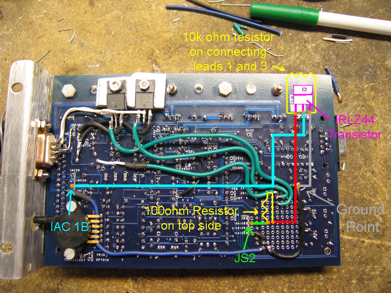
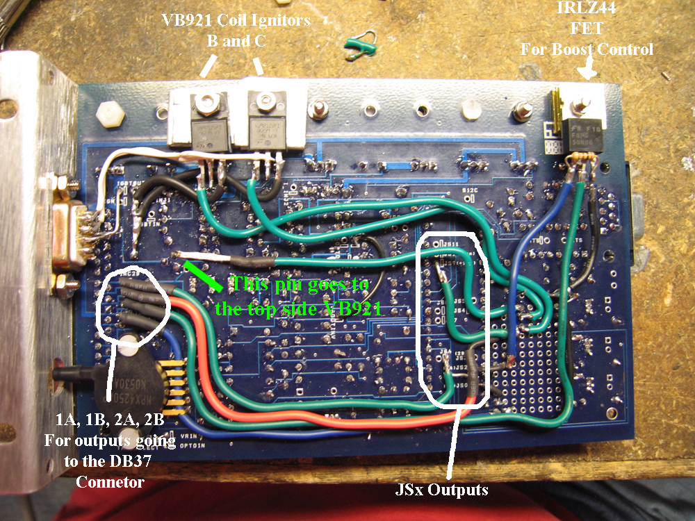
If you see in my diagram at
www.mkosonen.com/mattsmswiring.gif you will see that JS2 (jumper location on the v3.0 board) connects
to the IRLZ44 mosfet via a 100 ohm resistor. I used the resistor to go from
the top side of the Proto Area down through a hole in the proto area then
across to the JS2 jumper location. Then The other side of the resistor I went
through another hole in the proto area (next to the first hole) and soldered
the wire that goes to teh IRLZ44 mosfet. You will need to mount the IRLZ44
mosfet to some kind of heat sink, I used an old R/C Car speed controller heat
sink chopped in half, but you could use just a small piece of 1/16" aluminum,
and bolt it on the bottom side of the board with one of the bolts that goes to
the top side heat sink. You can see in my post on this page
http://www.e30tech.com/forum/viewtopic.php?t=26128. The 10k ohm resistor
goes from leg 1 to leg 3 on the mosfet, but you must keep it really close to
the mosfet since there wont be a whole lot of room when you slide the MS case
back on. Leg 3 of the IRLZ44 goes to ground, and I used the Ground location
of the proto area (2 jumper holes). Then then the middle leg goes to IAC
1B which lets it pass through the DB37 connector and out to the solenoid mounted
under the hood. To better let you see this, here are 2 board images.
Image 1 and
Image 2
As for code mods, if you have MT2.25 Release then go to Basic Settings, then
down to Codebase and Output Functions. In there you will see X4 (JS2), turn
it to Boost Control. Once you turn that on, you will then go to Advanced on
the main menu, then Boost Control. I used 19.5hz for the PWM rate, but I hear
it will react better with a higher PWM, so you might want to fiddle with
that. I used a 10ms controller update, and 50% proportional gain, and 10%
differential gain. Increasing voltage will increase boost. Set the closed
loop kPa limit to 0 kPa, this enables MS to use the duty cycle targets at all
times. MS has the ability to search out a certain boost pressure per rpm and
per throttle position, but its kinda iffy still. Duty targets are proven, and
are what most electronic boost controllers use.
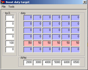
Go to the Boost Duty Targets in the Advanced tab,
and you will see a table. Basically, the duty you are entering is how long
the solenoid stays open compared to how long it stays closed. 50% duty means
it is open the same amount as it is closed. 0% duty means the solenoid
is open at all times, and 100% means it is closed all the time. 0% means that
your wastegate spring will be the lowest pressure, and 100% means that
whatever your turbo is capable of, it will hit that boost (overboost...). A
simple table to get started will only use 2 of the rows of duty. Try setting
it up similar to this table:
This will make your car act somewhat like a supercharger. As throttle position increases, boost will
increase to whatever boost 50% duty will be. If you want more boost, bump up
the 50% to 55% and keep going until you like what you feel. Once you know how
much boost you make at certain duty cycles, you can set up the TPS to react to
how you want. If you want a lot of boost at low rpm and low TPS, then make
the table however you'd like, something like this:
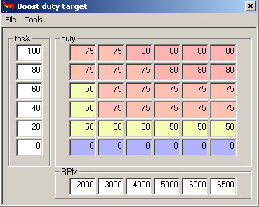
Just watch out, there will be a certain point in the tuning of the duty targets that the boost may jump
up a lot with a small change in duty %, this is normal, just be careful when
tuning this not to go overboard, wind it out slowly so you don't overboost.
|
